Hydraulic Fracturing Workflow Enhancements
AccuMap 3D Wellbore Viewer automatically positions basic downhole objects within a flat frac plane or as a structural surface drapery to allow you to focus on the inter-wellbore communication risk analysis, instead of manually browsing raw data sets.
The following objects can be optionally positioned along each wellbore:
- Multi Stage Fracs (dark blue) and Perforations (light blue) for horizontal wells based on completions.
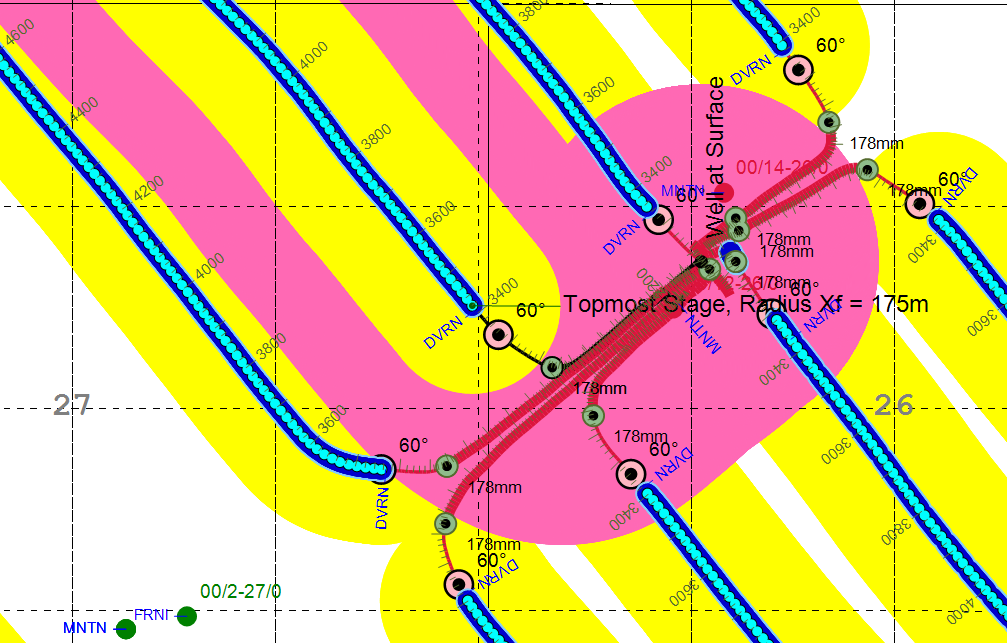
- Stimulated Area (bright yellow) shows the fracture Xf half-length buffer around each frac stage in horizontal wells (if the app detects system or user fracs for the subject or offset wells). Using the Frac Geometry Dialog you can hide Stimulated Areas for Out of Frac Plane offset wells with bottom holes that are significantly shallower or deeper than the subject well undergoing hydraulic fracture.
- Inclination Marker (pink ball) - First point in a horizontal well trajectory where the inclination reaches the user defined value.
- MD Labels posted every 200 meters starting from 45° inclination; MD Scale with major (100m) and minor (20m) ticks rendered starting from 10° inclination.
- Casing Shoe (olive ball) and associated Casing Diameter optionally posted starting from 10° inclination.
- Casing Width - app automatically changes the thickness of the wellbore based on the casing diameter.
- Tops placed starting from 75° inclination. If there are no such tops, the last top with the maximum MD is placed regardless of the inclination.
- SLOTS and OPHOLE completions (not shown above) can be optionally rendered along the horizontal wellbore.
- Ellipses of Uncertainty (EOU) formed from azimuthal, inclination, and measured depth errors can be incorporated in the proximity and risk analysis. 2D EOU is rendered with the Long Axis corresponding to Spatial Uncertainty and the Short Axis corresponding to TVD Uncertainty.
Hide 3D Wellbores using the corresponding check box in the ribbon toolbar.
 Related Topics